Choosing the right Air Pressure Gauge is not a minor purchasing decision. It affects safety, energy use, maintenance, and measurement confidence. The U.S. Department of Energy reports that compressed-air systems can consume 10% to 15% of industrial electricity. A poorly selected gauge can hide leaks, pressure drops, or unstable equipment. Small errors become expensive.
NIST Technical Note 1297 explains that measurement results must include uncertainty, not just a displayed number. Pressure-metrology expert Dr. Michael de Podesta expresses the principle clearly: “If you do not know the uncertainty, you do not know the measurement.” That warning deserves attention. A gauge with a bright dial may still be unsuitable for vibration, pulsation, heat, or corrosive media. I have also seen specifications treated as guarantees, although installation conditions can change performance quickly.
This guide presents seven practical tips for selecting an Air Pressure Gauge. It considers pressure range, accuracy, dial size, connection type, materials, calibration, and operating environment. The recommendations align with established guidance, including ASME B40.100 and NIST measurement principles. Expect useful details, such as keeping normal pressure near the middle of the scale and checking whether a snubber is needed. No selection method is perfect. However, careful questioning can prevent a gauge from becoming the weakest link in a reliable system.
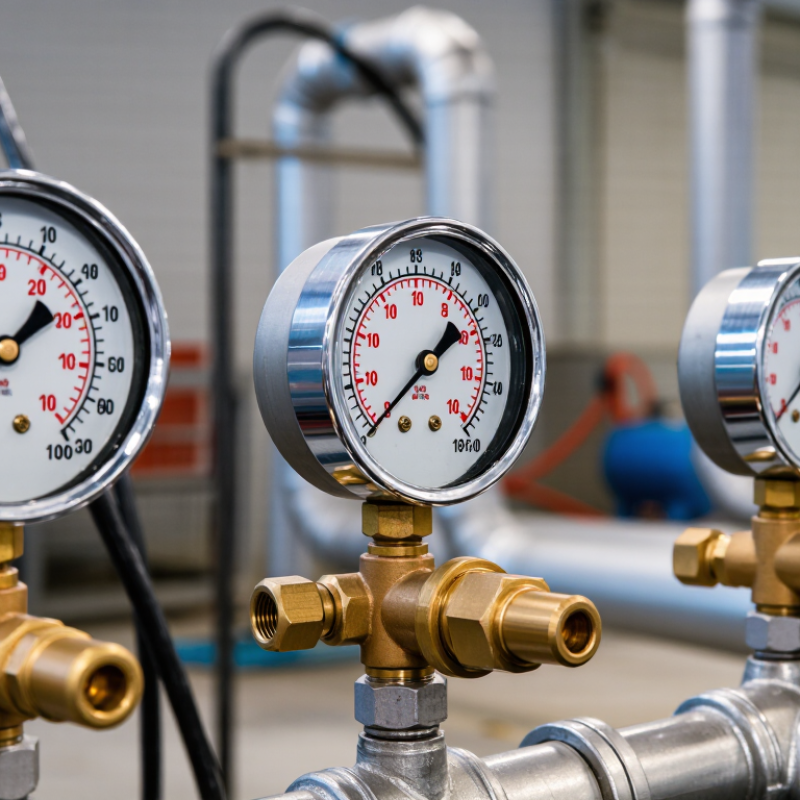
Choosing an air pressure gauge starts with the working range, not the dial size. Set the normal operating pressure near the middle of the gauge’s full scale. A 0–16 bar gauge used at 2 bar may provide poor readability and unnecessary accuracy loss. A 0–4 bar gauge is usually more suitable.
Leave room for pressure spikes. A practical rule is to keep normal pressure below 75% of full scale, especially where compressors cycle frequently. The U.S. Department of Energy reports that compressed air can consume 10–30% of industrial electricity, so small control errors can increase operating costs. Pressure stability matters.
Accuracy must match the process risk. ASME B40.100 expresses gauge accuracy as a percentage of span, not simply the displayed reading. For a 0–4 bar gauge with 1% span accuracy, the possible error is about 0.04 bar across the scale. That may be acceptable for general line monitoring, but not for calibration or sensitive pneumatic control. NIST Technical Note 1297 also recommends evaluating measurement uncertainty across the complete measurement chain. The gauge is only one part.
Consider temperature, vibration, pulsation, and installation position. A filled case can reduce pointer movement in vibrating areas, but it is not a substitute for correct range selection. I would also question catalog accuracy claims made without test conditions. They can look precise. Reality is less tidy. Calibration records, connection quality, and operator reading habits can alter the result.
| Tip | Application or Requirement | Recommended Pressure Range | Recommended Accuracy | Dial Size | Useful Selection Notes |
|---|---|---|---|---|---|
| 1 | General compressed-air service | 0–10 bar (0–150 psi) for systems operating around 6–8 bar | ±1.0% to ±2.0% of full scale | 63–100 mm (2.5–4 in) | Keep normal operating pressure near the middle portion of the scale. Avoid selecting a range only slightly above normal pressure. |
| 2 | Low-pressure pneumatic control or instrumentation | 0–1 bar (0–15 psi) or 0–2.5 bar (0–30 psi), depending on the system | ±0.5% to ±1.0% of full scale | 63–100 mm (2.5–4 in) | A lower full-scale range improves readability and resolution when the measured pressure is low. |
| 3 | Compressor discharge or plant-air header monitoring | 0–16 bar (0–230 psi) for systems typically operating at 8–12 bar | ±1.0% of full scale | 100–160 mm (4–6 in) | Verify that the gauge range is above the maximum operating pressure and any expected pressure peaks. |
| 4 | Filter, regulator, or dryer differential-pressure monitoring | 0–0.6 bar (0–10 psi) differential range is common; confirm the equipment specification | ±1.0% to ±2.0% of full scale | 63–100 mm (2.5–4 in) | Use a differential-pressure gauge when comparing upstream and downstream pressure rather than measuring line pressure alone. |
| 5 | Pneumatic actuator or control-valve supply | 0–6 bar (0–90 psi) or 0–10 bar (0–150 psi), based on actuator requirements | ±1.0% of full scale; use tighter accuracy for control verification | 63–100 mm (2.5–4 in) | Check the actuator’s minimum and maximum supply pressure, then select a range that provides readable operating values without over-ranging. |
| 6 | Leak testing or pressure-decay testing | Select the narrowest suitable range; examples include 0–1 bar or 0–2.5 bar | ±0.25% to ±0.5% of full scale, depending on the allowable test tolerance | 100–160 mm (4–6 in) or a digital display | Gauge accuracy should normally be significantly better than the permitted test error; include temperature effects and resolution in the uncertainty budget. |
| 7 | Portable troubleshooting or calibration checks | Choose a range that covers the test point while keeping it within approximately 25%–75% of full scale | ±0.25% to ±0.5% of full scale for verification work | 100–160 mm (4–6 in) or digital display | Confirm calibration traceability, zero stability, unit selection, and the required recalibration interval before use. |
Use gauge pressure for systems measured against surrounding air. Choose absolute pressure for vacuum work or sealed chambers. Use differential pressure between two points, such as across a filter. The wrong reference can produce a convincing, misleading reading.
A Bourdon-tube mechanism handles many general industrial applications. A diaphragm mechanism can respond well to lower pressures and cleaner air. Dry gauges are simple and economical. Liquid-filled gauges reduce pointer vibration near compressors.
Digital gauges provide clear numerical readings. They can help when exact values are difficult to read on a dial. However, batteries may weaken, and electronic readings can drift. A bright display is not enough when condensation covers the window.
Keep normal operating pressure near the scale’s middle. Avoid operating continuously near the upper limit. Leave room for pressure spikes. A small safety margin matters.
Check the connection position, available space, and pipe direction. A rear connection may suit a panel installation. A lower connection can simplify pipe routing. Small detail. Big consequence.
Check the stated accuracy, calibration interval, and test method. A traceable calibration record supports dependable inspection readings. It does not replace periodic verification against a traceable reference. A gauge may be accurate but poorly calibrated.
Choose markings visible from the operator’s normal distance. Large numbers help in vibration or changing light. The pointer should move smoothly near common readings. Mixed pressure units can create avoidable errors.
Check resistance to vibration, moisture, dust, temperature changes, and impact. Confirm that seals tolerate moisture, oil traces, and working temperatures. Ask about calibration services, replacement parts, and protective covers. Record installation dates and recalibration results. I might overestimate the protection needed. Recheck the real environment.
Choosing the right Air Pressure Gauge starts with clearly defining your pressure range and required accuracy. Select a gauge that can safely cover the normal operating pressure while still providing precise readings. Next, consider the measurement application and choose the most suitable gauge type, whether for routine monitoring, testing, or specialized equipment. The connection size, mounting style, and installation method should also match your system to ensure secure fitting and convenient access.
Material compatibility is equally important, especially when the gauge may encounter moisture, chemicals, vibration, temperature changes, or outdoor conditions. Review the construction materials and environmental resistance before making a decision. Finally, compare calibration options, dial or display readability, response performance, and expected service life. A dependable Air Pressure Gauge should remain easy to read, stable in demanding conditions, and simple to maintain. Evaluating these factors together helps improve measurement accuracy, operational safety, and long-term value.

 Accuracy Instrument